Hardware for Collecting
|
|
|
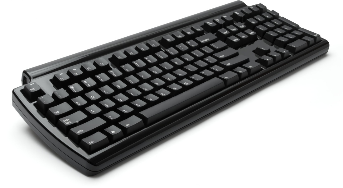
The Keyboard
The keyboard is a collection of switches, each on its own individual circuit that represents a unique key. These switches are operated by the user by depressing the keycap over each switch. This presses a carbon button underneath the cap which completes the circuit signalling that the key has been pressed. Once pressed, the keycap is then returned to its normal position by the plastic dome underneath the key normally causing audible feedback such as a click. The completed circuit sends an electrical charge to the keyboard’s microchip, where it is detected as a change in voltage. This data is then analysed by the microchip and converted into a binary scan code which represents that key and whether the key is either pressed or released. Once processed, the data is stored in the keyboard’s internal memory ready for transmission. |
|
The scan codes are then transferred to the computer’s motherboard along the keyboard’s interface cable. This cable contains four wires, all necessary for the operation of the keyboard. Two of the wires power the keyboard, another controls the rate of data transfer, while the last cable is used for transferring data.
Once the scan codes arrive at the motherboard, they are stored in the system’s memory and the system’s operating system (OS) is notified through an interrupt request. The scan codes are then examined by the OS, assisted by the keyboard device driver, which then performs the appropriate action. Typically, the scan codes are converted into a representation that contains the corresponding ASCII code along with any modifier keys, such as control or shift, that were pressed. This data is then passed onto the currently active application, where the application decides what to do next, or is intercepted by the operating system for a system task such as switching between applications.
Once the scan codes arrive at the motherboard, they are stored in the system’s memory and the system’s operating system (OS) is notified through an interrupt request. The scan codes are then examined by the OS, assisted by the keyboard device driver, which then performs the appropriate action. Typically, the scan codes are converted into a representation that contains the corresponding ASCII code along with any modifier keys, such as control or shift, that were pressed. This data is then passed onto the currently active application, where the application decides what to do next, or is intercepted by the operating system for a system task such as switching between applications.
The Mouse
The basic design of the mouse was invented by Douglas Englebart in 1964 and is still largely used today as the primary and most popular method of controlling a computer. The simple design of the mouse collects movement data in two dimensions to typically control the movement of the onscreen curser. The mouse also contains inbuilt buttons for added control. The mouse collects movement data in two different ways, a rolling ball or through optics.
The basic design of the mouse was invented by Douglas Englebart in 1964 and is still largely used today as the primary and most popular method of controlling a computer. The simple design of the mouse collects movement data in two dimensions to typically control the movement of the onscreen curser. The mouse also contains inbuilt buttons for added control. The mouse collects movement data in two different ways, a rolling ball or through optics.
|
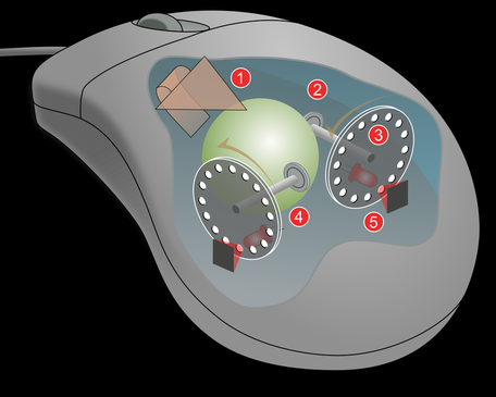
The rolling ball design collects movement data through two
rolling shafts that rotate as the ball in the mouse rotates. The shafts each
collect the magnitude of movement in opposite directions corresponding to the
x-y axis. At the end of each shaft is a disk with slits in it that rotates as
the shaft rotates. The movement data is converted into digital data by a pair
of 2 LED lights and 2 LED sensors positioned on opposite sides of each disk so
that as the disk rotates pulses of light are detected by the sensors and
interpreted as magnitude of movement as well as direction of movement along
that axis by the mouse’s internal controller. This data is then transferred to the
computer in the form of pulses detected in binary form at a rate of
approximately 40 times per second.
The downside of its design is that the ball picks up any dust and debris that may be present on the desktop which rapidly accumulates on all the moving parts. This can cause the mouse to stop functioning properly or stop functioning all together. Because of this, a second, more efficient, design of mouse was created; the optical mouse. The optical mouse eliminates all the mechanical parts and replaces them with a red LED, an image sensor as well as a digital signal processor. The light from the red LED is reflected off from the surface of the desktop and onto the lens of the image sensor, which is essentially a mini digital camera. The sensor takes a picture of the desktop around 1500 times a second and sends the pictures to the digital signal processor. Here the direction and magnitude of movement is detected by comparing features in each successive image. Because of this, the optical mouse has increased speed and precision for calculating the movement of the mouse. |
|
All mice also collect data through its buttons and the scroll wheel. This data is collected as either the button is clicked or is not clicked. For the case of the scroll wheel, the data is collected as if the wheel is two buttons combined. Since the wheel does not rotate smoothly but rather rotates in a series of clicks, the wheel can either be clicked forward or not clicked forward, or clicked backwards or not clicked backwards. All data from button clicks are transferred to the computer in binary form with 1 representing a click and 0 representing no click.
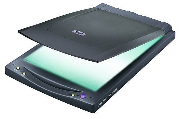
Scanners
Scanners are essentially a type of camera, gathering image data by collecting data from the light around and converting it into binary data. This is done by detecting the amount of reflected light of the surface of the image to be scanned. Typically darker areas reflect less light than lighter areas which is the main principle behind scanning images. Scanners come in numerous forms; each designed to perform a specific task, such as barcode wands, laser scanners and charged coupled devices.
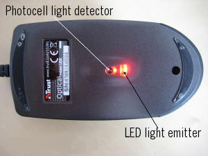
Barcode wands use LED to illuminate a small spot on the barcode. As the wand moves along the barcode its photocell picks up high and low amounts of reflected light which is then converted into white or black based on the light picked up (more light means white). The currents are then converted into binary using an analogue to digital converter.
Scanners are essentially a type of camera, gathering image data by collecting data from the light around and converting it into binary data. This is done by detecting the amount of reflected light of the surface of the image to be scanned. Typically darker areas reflect less light than lighter areas which is the main principle behind scanning images. Scanners come in numerous forms; each designed to perform a specific task, such as barcode wands, laser scanners and charged coupled devices.
Barcode wands use LED to illuminate a small spot on the barcode. As the wand moves along the barcode its photocell picks up high and low amounts of reflected light which is then converted into white or black based on the light picked up (more light means white). The currents are then converted into binary using an analogue to digital converter.
|
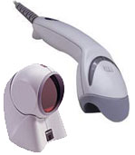
Laser scanners use high intensity beams of light that can be
precisely directed to a particular point. These kinds of scanners have the
ability to operate at larger distances than normal such as 30 cm. When
scanning, the laser scanner continuously moves or rotates its mirror reflecting
the laser beam at different angles which will eventually hit a barcode and then
scan it whether the barcode is rotated or positioned little bit off centre from
the scanner. In this process it also
picks up any reflected light it emits and converts it into binary data based on
the amount of light reflected back to the photocell. This type of scanner is
commonly used in supermarkets.
Charged Coupled Device scanners use a moving LED light source to reflect light off the image or barcode and a lens that focuses the reflected light on its photocells that detect the level of light reflected. The light detected is converted into an electrical current with more light being a higher current. The current usually goes through an analogue to digital converter to output the data into binary. CCD devices typically have a high image quality and are used in devices such as digital cameras, video cameras as well as flatbed scanners. |
|
|
Microphones
Microphones are a tool for collecting audio data from sound waves and converting it into electrical currents so it can be used by other digital devices. This is done through sound waves contacting and vibrating the diaphragm inside the microphone. The two most popular types of microphones are dynamic and condenser microphones. Dynamic microphones rely on magnetism to convert sound waves from the diaphragm into electrical currents. The diaphragm on this microphone is attached to a coil of wire which vibrated with the diaphragm. The vibrating coil either surrounds or is surrounded by a magnet. This causes the moving coil to alter the magnetic field produced by the magnet which also causes a current to flow though the coil of wire. The current flowing through the wire varies as the coil moves which represents the change in the sound waves. Condenser microphones collect sound data by altering the distance between two plates. The first plate is the diaphragm which vibrates in sync with the sound waves; this changes the distance between the diaphragm and the static back plate behind it. The closer the diaphragm is to the back plate the more electrical current that flows from the diaphragm into the back plate. The constant variation in electrical current is what creates the digital 'sound waves'. This microphone requires a constant power source to operate or a permanently magnetic diaphragm. |
|
|
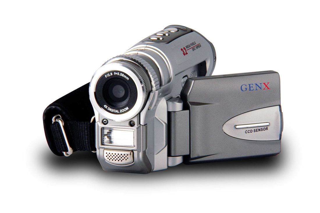
Video Camera
The video camera is a combination of a microphone with a high performance digital camera to capture many pictures per second. Video cameras operate largely in the same way as a camera with a few modifications. Video cameras, unlike still cameras, have two layers of CCDs to handle the amount of images required to be captured per second to make video. The layer of CCDs at the front, nearest to the lens of the camera, is the layer that captures the image. Once captured, the image data is then transferred onto the second layer of CCDs, which are behind the first layer, ready to be read and processed. This frees up the first layer of CCDs to capture another image. |
|
